CN 110 Pull Levers, & WWS Western Dump Cars
A lot has happened since the last study – I retired! Somewhat surprisingly, I’m finding less time to review studies than when I was working. I’m spending more time on MR and RR investigations but can’t seem to find the time to review them and summarize them in the pic collections I’ve been doing. But let’s get one started.
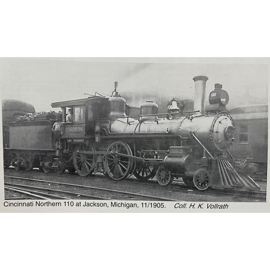
Two recent topics have captured my interest: My modeling of CN 110 is starting to approach a closure point. But each time I look at a photo, I find something that I feel needs an investigation. (Classic the more you know, the more you know you don’t know.) Check out the photo of CN 110 (one that I’ve posted several times).
I’ve been working on the pilot and started looking for the pull levers. (The levers that pull the pin on the coupler.) Since the photo was taken in 1905, couplers were still transitioning. Most were Janney style, but not all types could intercouple. The modern Janney style couplers weren’t standardized until 1913. When I couldn’t clearly identify a modern style pull lever in the CN 110 pic, and I found that the couplers had not been standardized when the photo was taken, I had to dig deeper.
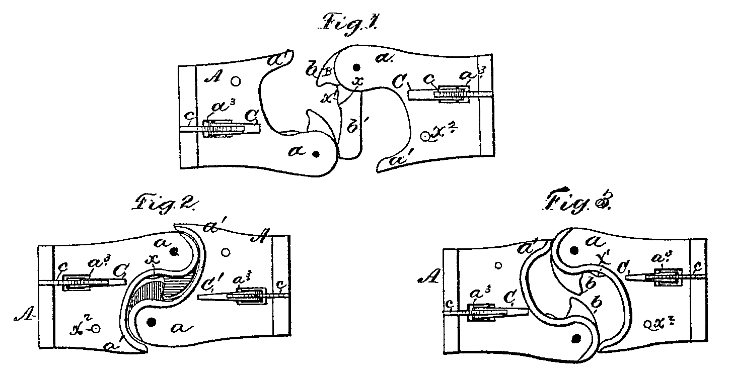
Janney couplers were first patented in 1873 by Eli H. Janney<https://en.wikipedia.org/wiki/Eli_H._Janney>. The original Janney couplers were rather finicky and were reportedly annoying to open and close. This design was obsolete by 1900. Here are sketches used in the original Janney patent filing.
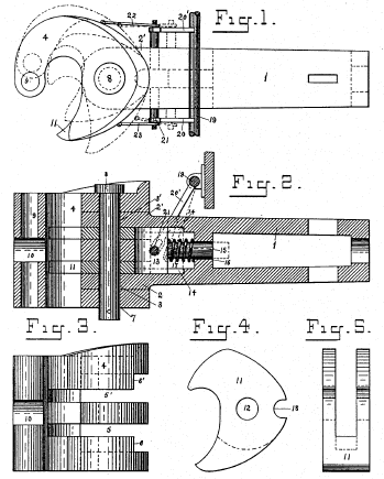
In the latter 1880’s the Master Car Builder’s Association (MCB) was faced with choosing a standard from the multitude of mutually incompatible automatic coupler designs that existed. They did not choose a single design but favored Janney’s. Hence, the mating profile only was established based on a modified Janney coupler. Thus, the MCB standard initially specified only the interface between MCB automatic knuckle couplers, leaving all other aspects to open competition between manufactures. The MCB continued to modify and add to the standard, but in 1899, a coupler identification chart showed 78 MCB coupler varieties that had mutually incompatible knuckles. One such coupler design was the Beard coupler. Andrew Beard was amongst many inventors that improved upon the Janney design. This diagram is from Beard’s 1897 coupler patent.
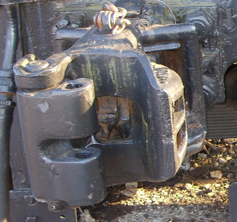
Here is another of the multiple incompatible couplers of the late 19th century, an MCB Type 5 coupler circa 1893. The split knuckle accommodates link and pin couplers. The vertical hole in knuckle accommodates the pin. Most of the MCB designs (even today) can accommodate link and pin coupling via the hole in the knuckle. This design could also have accommodated a buffers and chain coupler with an extra pin.
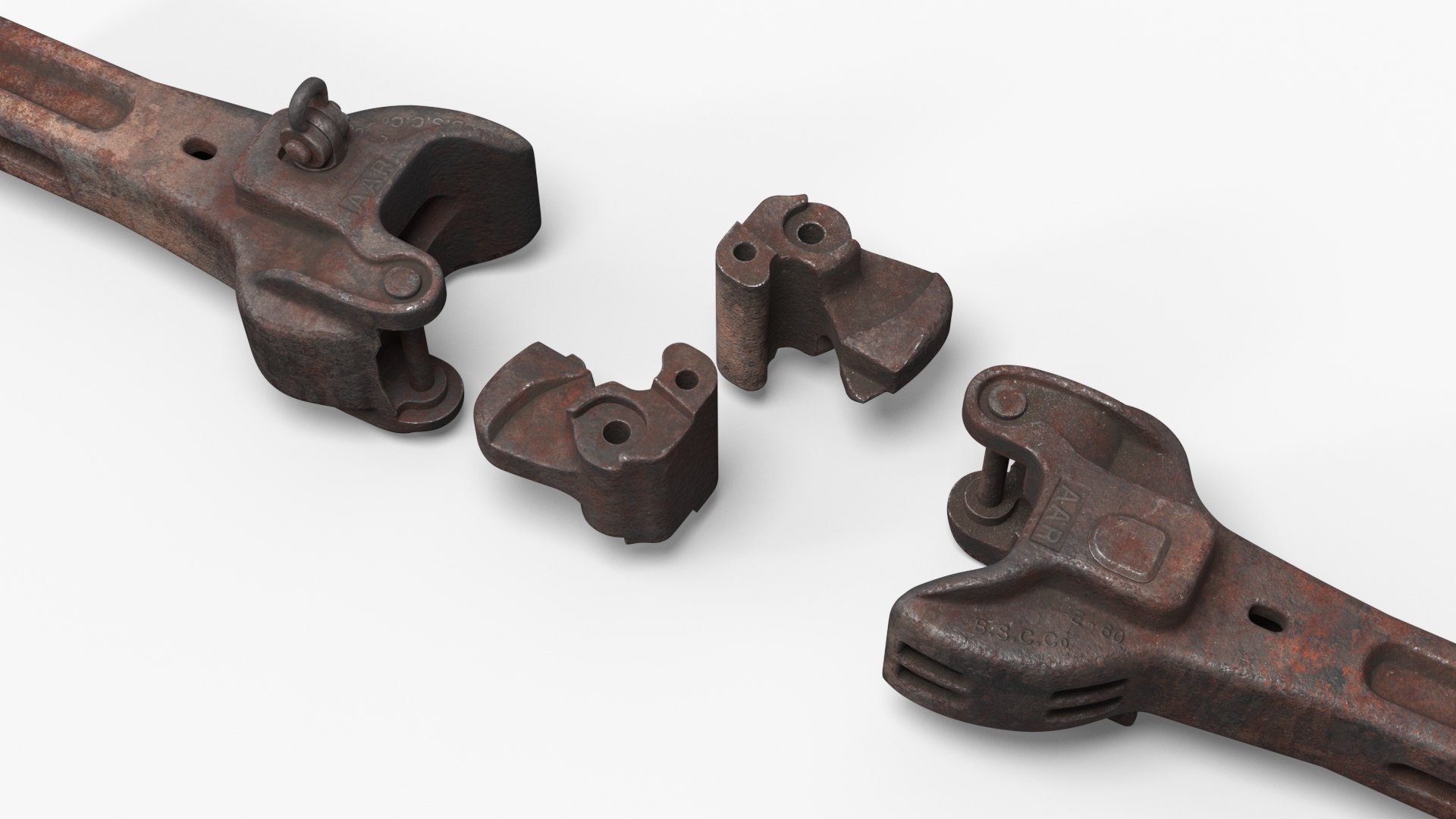
Further modifications and additions continued in the MCB standard until 1916 when what is now known as AAR type D coupler was recommended as the standard coupler. While current lingo talks about Janney style couplers, the correct designation is MCB or AAR type D. (There have been several modifications since 1916, but since the AAR type D was standardized, knuckles have been compatible.) I couldn’t find a good pic of type D couplers, but here is one of more modern type E couplers.
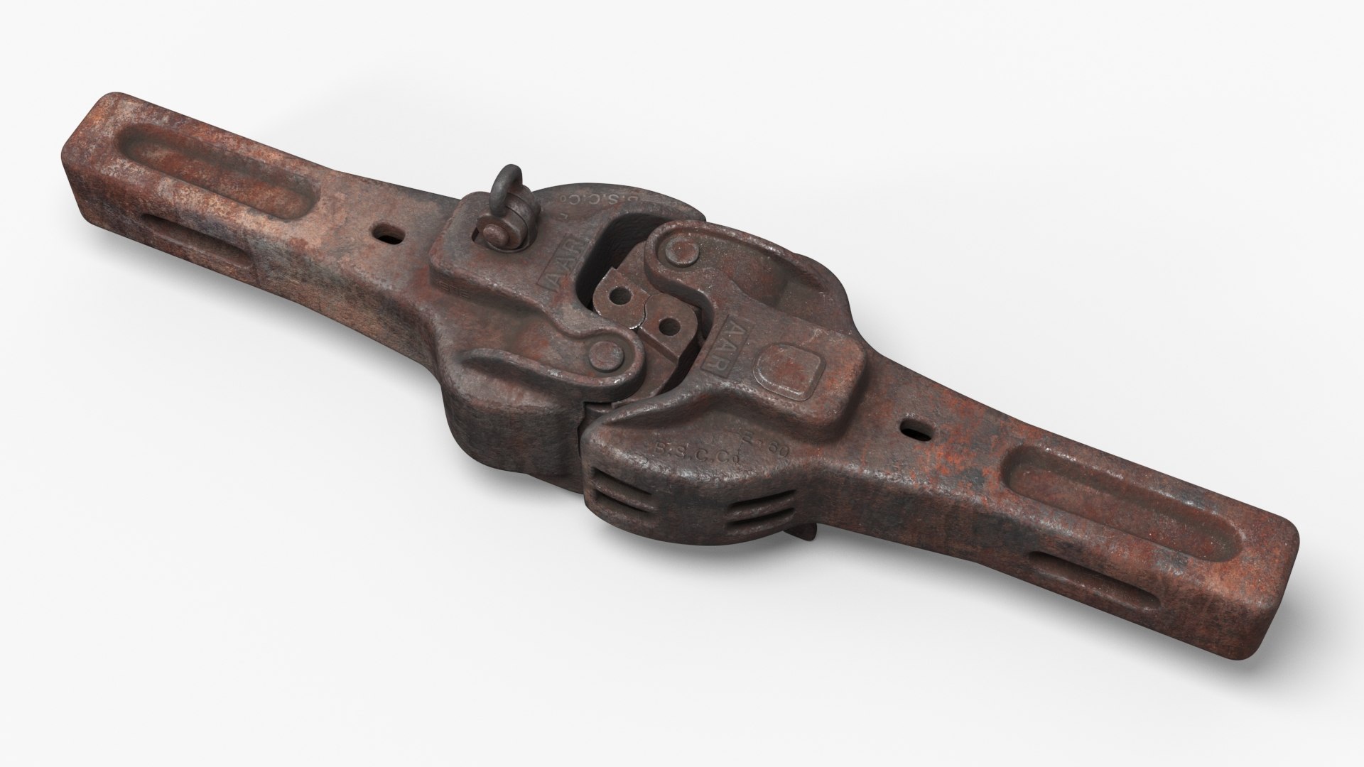
These two pics provide a great visual of type E couplers – both coupled and the parts involved. While looking like photos, these are actually the results of a 3D simulation called “old rusty”!
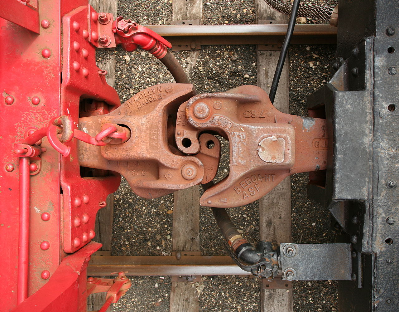
I found this great pic of an AAR Type E coupler (left) circa 1932, coupled to an MCB Type 5 coupler (right) designed in 1893 and part of the 1893 Railroad Safety Appliance Act. Note the difference in the pocket.
This pair of pics compare an old link & pin coupler to a modern type E coupler.
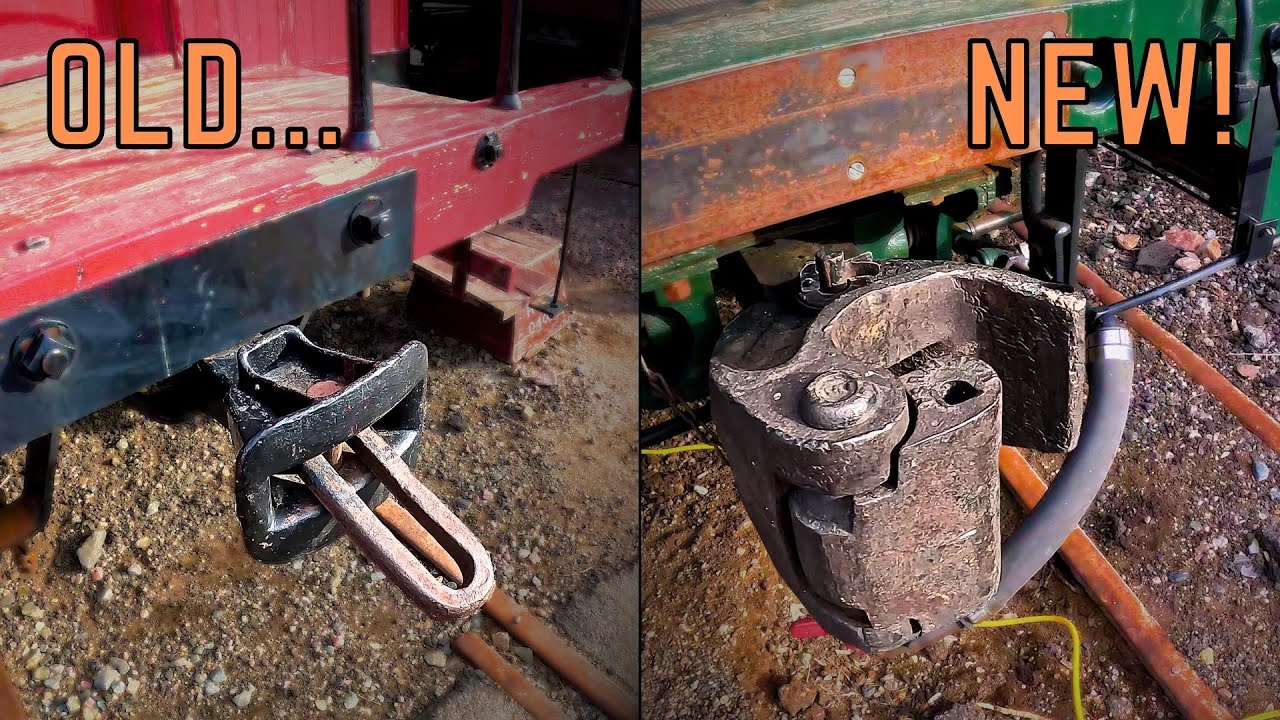
But my original question was less about the actual coupler, and more about the pull lever that pulls the coupler pin. (Because I’m an HO gauge modeler, I will be using Kadee style couplers in order to be compatible with the rest of my equipment. Kadees have a resemblance to Janneys. But, I hope to not have the incompatibility problems the railroads experienced in the early Janney coupler years!)
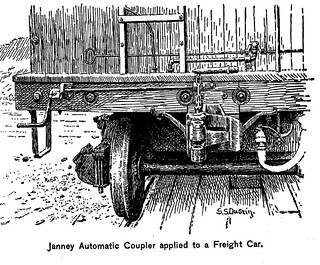
Here’s a drawing of a Janney coupler on the end of a freight car. Notice the pull lever on the left side running along the end beam.
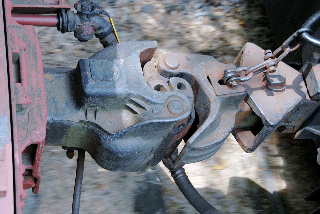
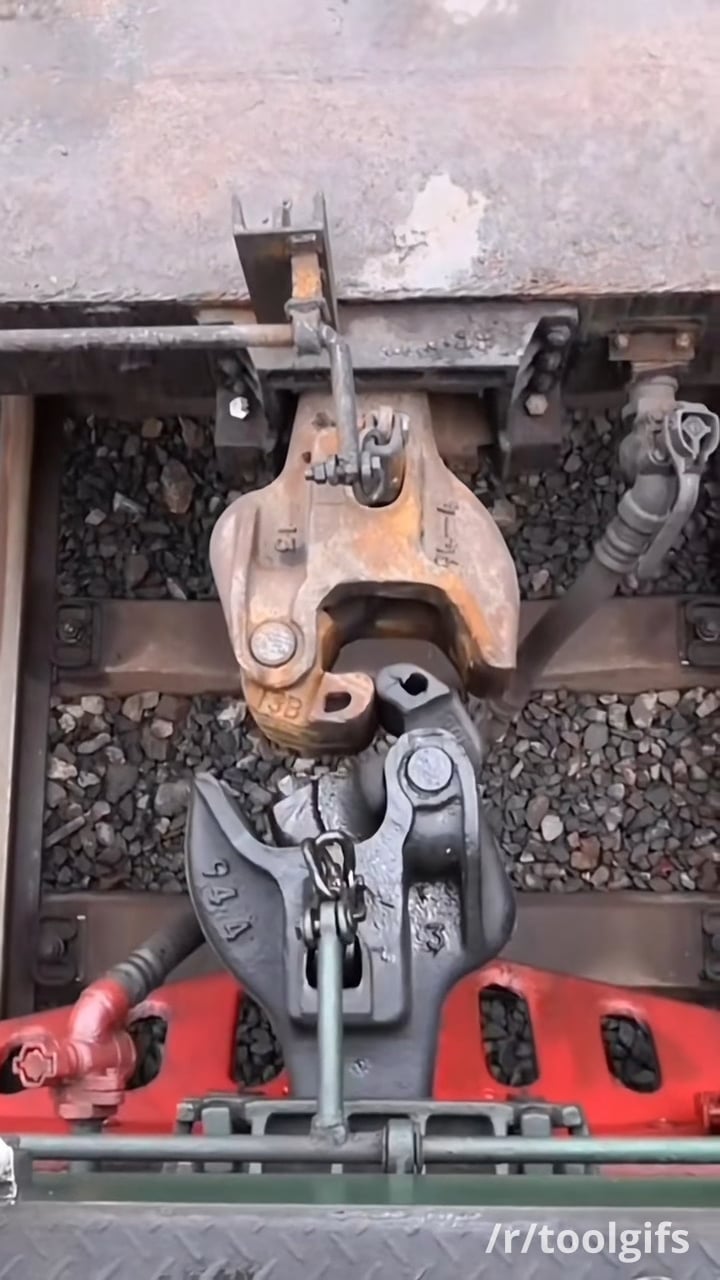
Here’s a great photo of type E couplers with the coupler pin pulled on the bottom one. Note that the coupler pin is linked to a rod that runs to the pull lever on the side of the car (pull levers are not shown in the photo). The top coupler pull lever is only on one side – the left side of the photo. I recently learned that most car couplers have levers on just one side. Since the two ends face opposite directions, with pull lever side standardized, you can walk down one side of the car, either side, and pull a coupler pin for each coupling in the train. In the pic, the bottom coupler has lever rods going towards both sides. This is likely a locomotive coupler; locomotive couplers tend to have pull levers on both sides.
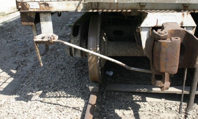
Here’s a great photo of a freight car coupler pull lever. Note that this one works from below the coupler.
Another great pic.
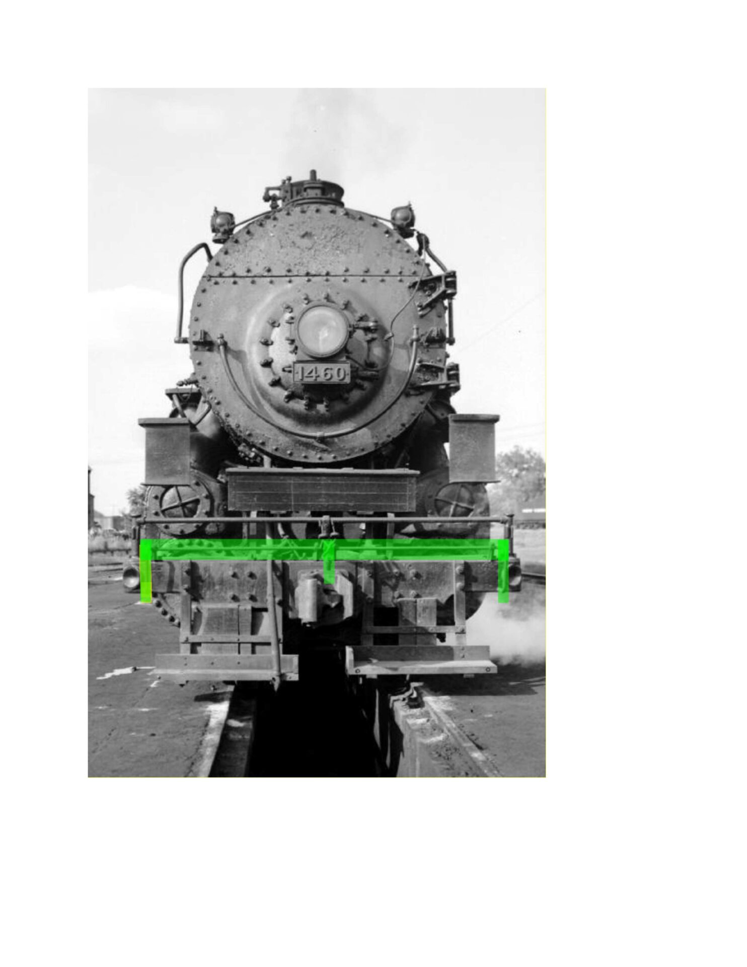
This is NYC 1460, a 2-8-2 Mikado that serviced the Cincinnati Northern, circa 1955. I’ve highlighted the pull lever and link to the coupler. The pic shows a standard modern steam pin pull system.
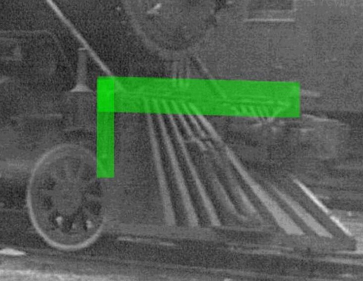
But, the pic of CN 110 was taken in 1905, before the couplers were standardized. The pull lever is hard to pick out and has a slightly different shape. (Again, I’ve highlighted what I think is the pull lever.)
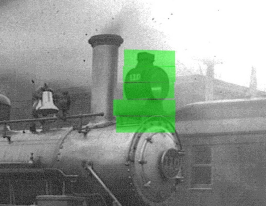
With the pull lever resolved, I’m still looking for the dynamo that would have supplied power to the arc lamp headlight. This cropped pic shows what appears to be an arc lamp. But again, I cannot find a dynamo that would be necessary to provide power to the arc lamp.
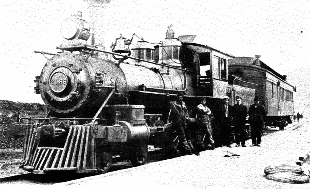
This is a pic of CN 110 sister locomotive NYC 7088 taken probably in the teens or ‘20s. It displays the same style headlamp – likely an arc lamp. This pic shows the fireman’s side – no dynamo. The first pic of this study shows CN 110’s engineer’s side – no dynamo. Other later pics of CN Americans show a dynamo between the steam and sand domes – there was no reasonable room between the cab and steam dome on these Americans. There is another possibility for location of the power source. Both of these pics show passenger equipment behind the loco – specifically a baggage car or combine. Some of my recent investigations have found that for early 20th century (and 1890’s) passenger equipment, there was a desire to electrify the cars (generally for lighting). Power was provided through two possible generators located in the first car of the train – the baggage car or combine. The first solution was providing a generator powered by the turning of the truck wheels. The second was by piping steam back from the loco and running a dynamo in the baggage car. Could a dynamo/generator in the first car also supply power to the arc lamp headlight? Currently, I’m thinking a dynamo in the baggage car was unlikely for the CN. My sources say that electric lighting in this era was expensive and used for only luxury passenger cars. The CN probably seldom if ever ran luxury cars. For now, I remain stumped on how the headlight for CN 110 was powered. I’ll likely complete the model loco without a dynamo, but…I have a few early dynamo castings in my bin that I can add to the model if I find where it was located!
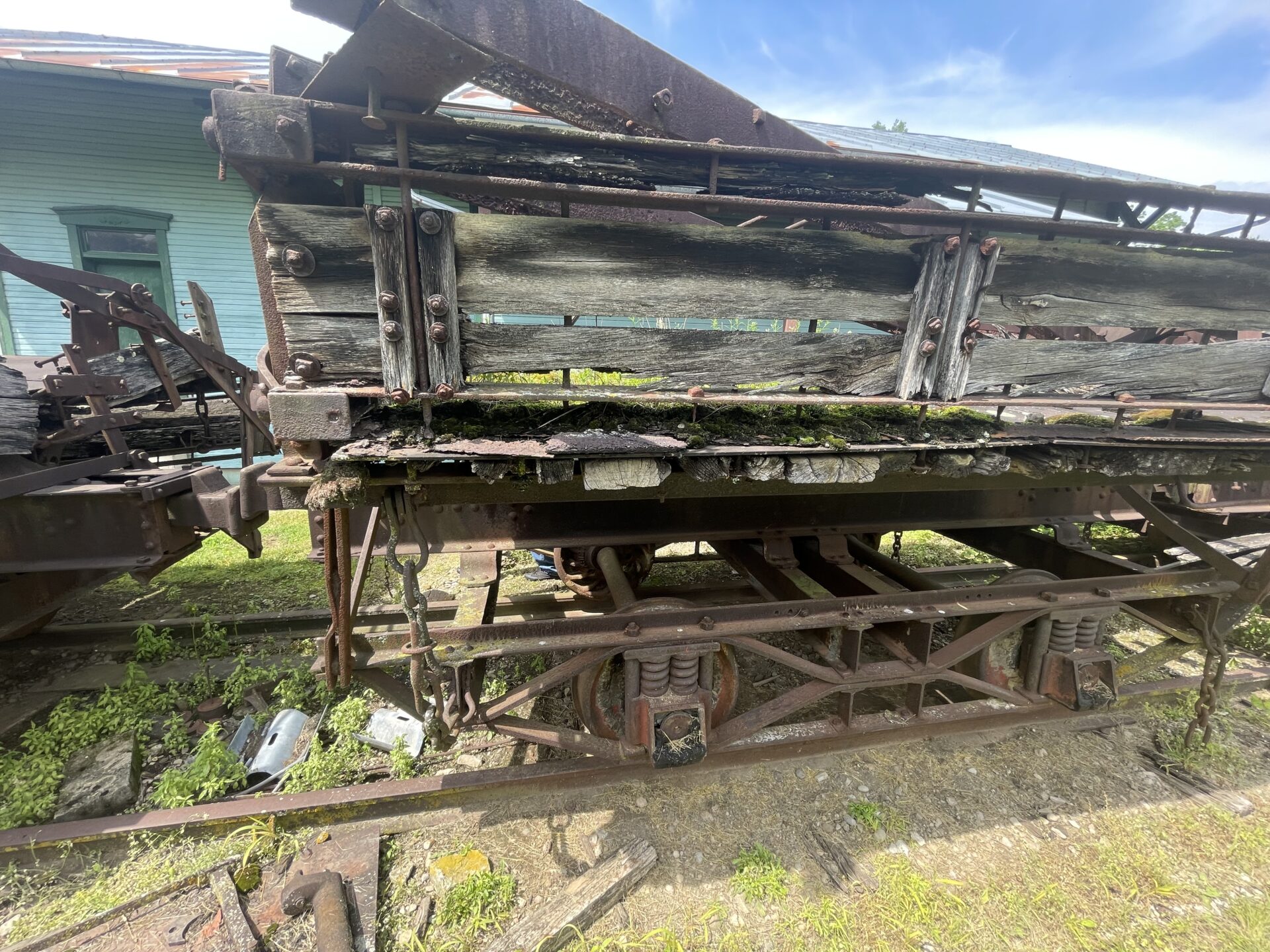
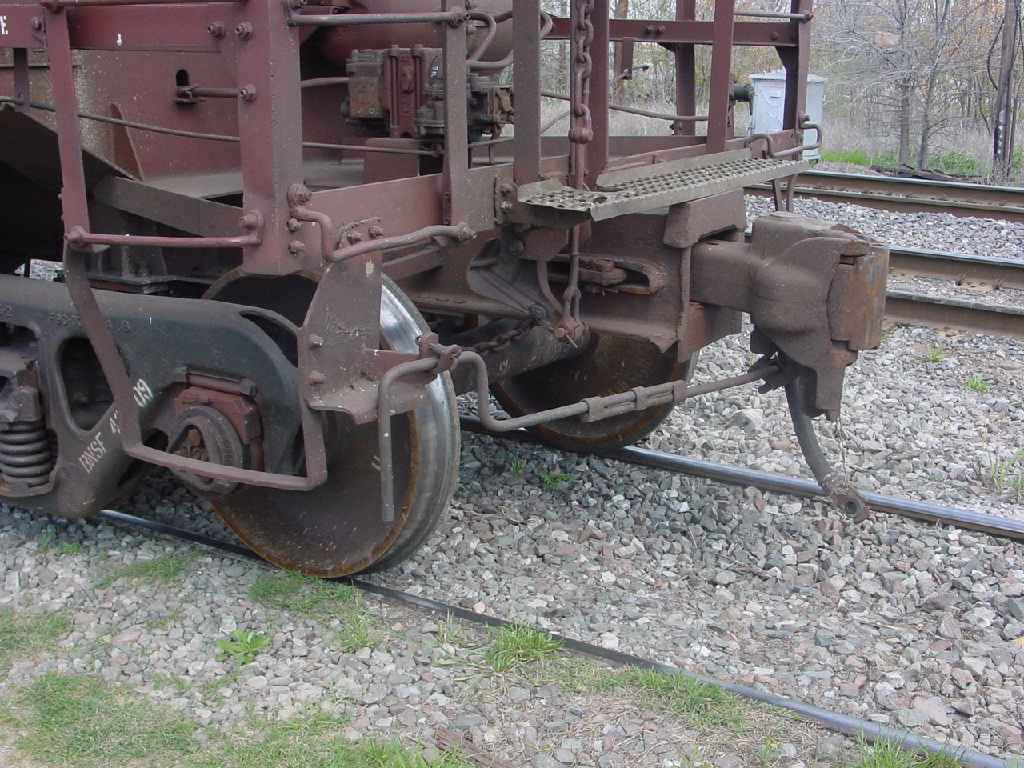
Finally, during our recent visit to Lewisburg, OH (for their annual ice cream social!), Monty and I spent some time looking over the old dump cars near the station. One of the historic society members had questioned us about the cars regarding a possible restoration project. Here’s a pic I took of one of the three cars.
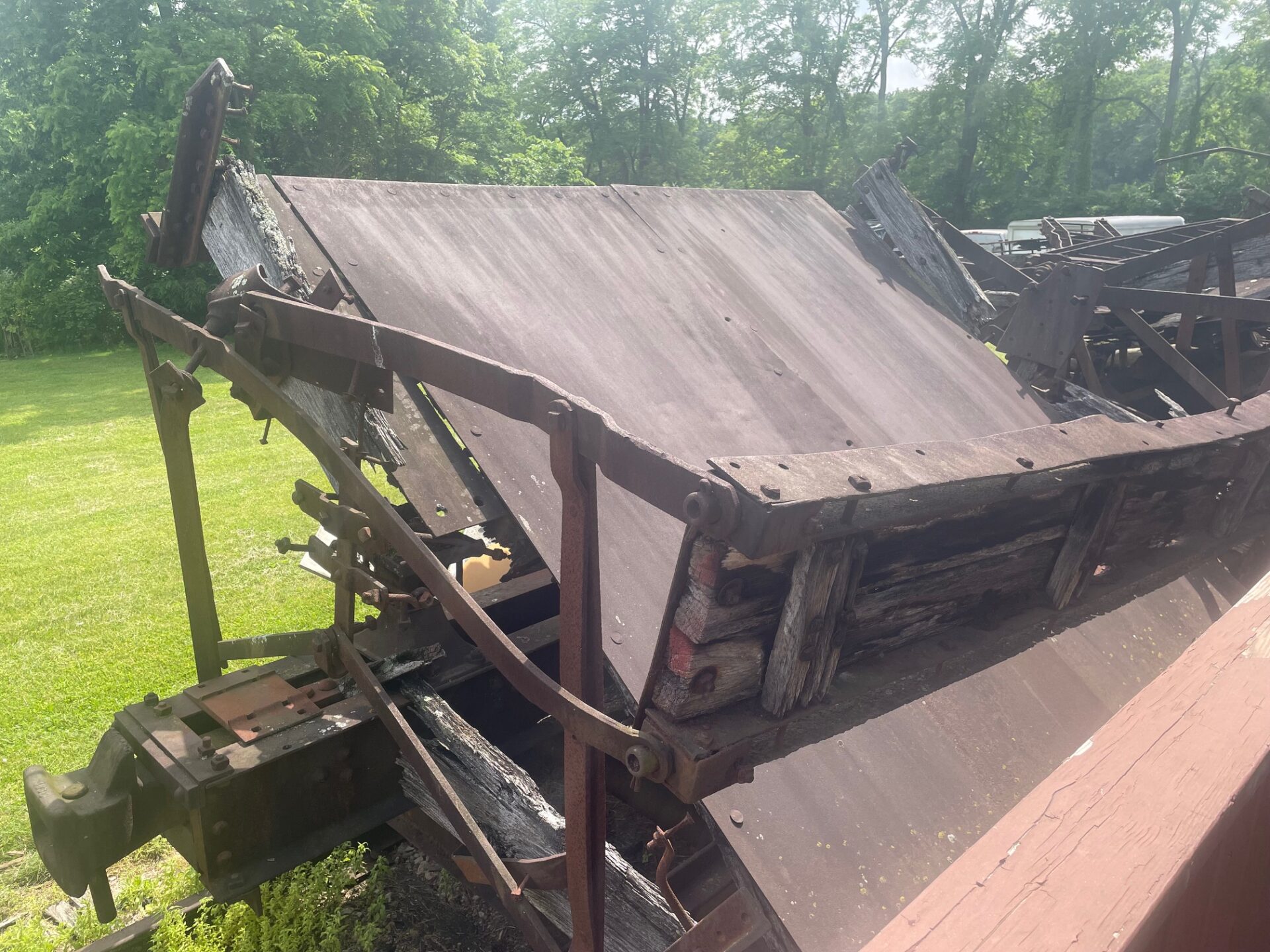
This pic shows one of the cars in the dump position. Referencing back to the coupler discussion, note the link and pin couplers. These cars were likely used only at the Lewisburg quarry, or on the Cincinnati Northern tracks as MOW equipment. With the link and pin couplers, they couldn’t be used in interchange service.
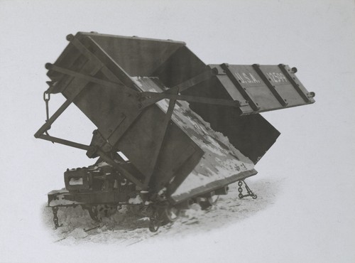
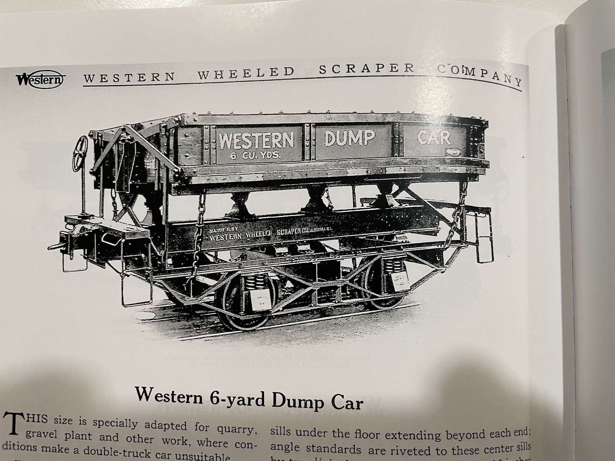
Monty found two clues as to the builder of these cars. WWS was embossed on the wheel journal covers, and Western Wheeled Scraper Co. was embossed on the wheels. A quick internet search produced info on the Western Wheeled Scraper Co. and their Western Dump cars. Here’s pic taken from some of the internet literature.
Further research located a published book by SilverLake Images LLC titled Western Wheeled Scraper Company: Western Dump Cars. This 82 page softbound book is a reprint of WWS Company’s Catalog No. 61 – Part 1. The SilverLake reprint was published in 2021, but I couldn’t find a published date for the original catalog. Roughly half the book covers single page descriptions with a photo of the manufactured equipment (90% dump cars). But the first half of the book provides pics of equipment in service along with descriptions of the types of service the equipment was being used for. Here’s the pic on the page which I believe identifies the model we found at Lewisburg. I still need to check dimensions between the Lewisburg cars and the catalog listing. Also, there’s some very minor differences.
Summary: I still have a lot of questions about CN 110 that I’d really like to resolve before I finish the model. However, I’m pressing forward with the modeling and nearing final touches. I hope to have a working loco with sound in the next couple of months. Any missing details can be added later!
Also, the Lewisburg dump car project has piqued my interest. Given the condition of the three cars they have, a restoration project will be a tedious effort. Most of the castings are in good shape, but some of the steel members are deformed, and the wood members will need to be replaced in entirety. They have three cars to work with, so the chances go up.
Thx,
Kevin
Comments